Monday, December 4, 2017

Laboratories Warm Up to Chilled Beams to Save Energy, Eliminate Reheat


Laboratories are not known for their energy efficiency. These spaces can consume up to 10 times more energy than office buildings, leading facility managers and engineers to prioritize finding ways to reduce energy consumption and operating costs – without sacrificing efficiency. One way to do that is by using chilled beam systems, which have grown increasingly popular in the U.S. in the last decade. Chilled beams have proven to be viable alternatives to traditional Variable Air Volume (VAV) systems, demonstrating energy savings upwards of 20% in laboratories compared to VAV Reheat.

To better understand how and why chilled beams are effective in laboratories, let’s examine the usage of these systems, strategies for effective design and operation in laboratory environments.

How Chilled Beams Work
There are two types of chilled beams, passive and active.


Passive chilled beams cool spaces using natural convective forces and include a heat exchange coil in an enclosure that is suspended from the underside of the building structure. Chilled water flows through the coil and cools the surrounding warm air; the denser cool air falls back into the space. Passive beams require separate air diffusers to carry dehumidified ventilation air into the space, usually at the floor level. For this reason, they are rarely, if ever, used in laboratories.


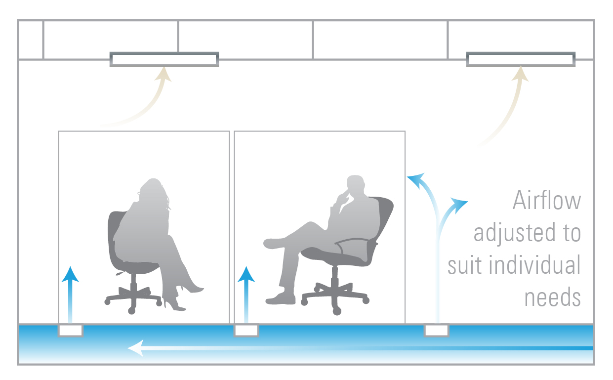
Active chilled beams rely on pretreated primary air delivered from central air-handling units (AHU’s) to pressurize a series of small induction nozzles within the chilled beam unit. These nozzles create jets of air causing room air to be induced across a coil where flowing water heats or cools this (secondary) air.

Both passive and active beams are designed to provide sensible cooling only with the latent cooling (i.e. space dehumidification) being accomplished by the central AHU’s. Depending on the lab use and loads, the primary air is delivered to the active chilled beams as constant or variable volume, with the cooling/heating output being controlled by either two position or modulating control valves to vary the water flow through the integral coils. Chilled beams can be integrated into suspended ceiling systems or hung from the structural slab for exposed use.


Because chilled beams provide most of a space’s sensible cooling, the central air handling system can be much smaller than usual since its primary purpose is to provide the ventilation air and latent cooling to the space. This effectively decouples the sensible cooling from the ventilation requirements. And since chilled beams have no moving parts, maintenance is limited to infrequent cleaning of the coils.

Laboratory HVAC Energy Use

The ventilation requirements for laboratories are different from the needs of a typical office building. Minimum ventilation rates are dictated by safety requirements rather than cooling or heating loads, while maximum rates are determined by either the make-up air requirements for the fume hoods or the sensible cooling requirements of the space (if the equipment cooling load is high). There are special requirements for laboratories where chemicals or gases as present as well. They cannot use recirculating AHU’s, so the ventilation air must be 100% outdoor air at all times.

Overall, these parameters can result in an air system sized for ventilation air changes rates from 6-to-12 or more, depending on the lab use and equipment loads.


A traditional "all-air" system will typically deliver cool air to the building at around 55°F when there is demand for OA dehumidification, or to satisfy the sensible cooling requirements of the highest load lab in the building. This often results in a mismatch of ventilation air and cooling requirements, forcing the zone VAV boxes to reheat the cooled air to prevent over-cooling the space when sensible loads are low. Even more reheating occurs when ventilation air is increased to provide make-up air for the fume hoods, resulting in lower efficiency.

And decreased efficiency hurts the bottom line: Energy studies have shown that cooling and reheating air can account for as much as 20% of the total HVAC energy costs in laboratories.

Eliminating Reheat and Saving Energy
Active chilled beams can help boost energy efficiency in a number of ways.


One is by eliminating most of the reheat energy resulting from decoupling ventilation and cooling demands. With active chilled beams the ventilation air can be delivered at a warmer temperature through a 100% outside air AHU, commonly known as a dedicated outdoor air system (DOAS). With the DOAS primary air set to around 65-70°F space overcooling is far less likely to occur, even in labs calling for high volumes of make-up air for the fume hoods. The water coils within the chilled beams provide cooling or heating capacity on a zone-by-zone basis. During OA dehumidification hours, the DOAS unit removes moisture by cooling the air to 55°F or below and is reheated with energy recovered from the exhaust air using enthalpy wheels, heat pipes or run around coils.


Another is through using water to transport heat, resulting in an air system size reduction of 60 percent compared to VAV Reheat. This feature reduces overall fan energy consumption and is ideal for laboratories with high sensible loads and low fume hood densities.


The increased efficiencies associated with chilled beams also help laboratories maximize their space. The reduced reheat and boosted transport efficiencies of water mean the main plant items (chillers, boilers and AHU’s) can be smaller than with a traditional system’s. The duct distribution system is also more compact, which reduces service congestion in the ceiling interstitial. Finally, a smaller system can translate into lower first costs for an HVAC system compared to VAV Reheat.

There is a challenge with using chilled beams in labs, however: the need for dual chilled water temperatures. Specifically, a low temperature circuit (LTCHW, 40-45°F) for the DOAS and medium temperature circuit (MTCHW, 56-58°F) for the active chilled beams. The most common strategy is to design a closed secondary loop separated by a plate and frame heat exchanger, ensuring that the LTCHW cannot accidentlly find its way into the active chilled beams. That could potentially cause condensation on the coils.

Building Humidity Control

The best chilled beam system designs equip the building with a small number of room dew point sensors. This allows the building management system to monitor the humidity across the building and reset the DOAS air dew point or reschedule the MTCHW loop temperature if the space dew point rises above a preset temperature. Facilities engineers can use the room dew point sensors to precisely control the amount of OA latent cooling at the DOAS unit to further reduce energy costs, an operational strategy that is more difficult to accomplish with a VAV Reheat system. Despite being used in early system designs; pipe mounted condensation sensors are rarely used today since room dew point monitoring provides enough advance warning of potential condensation.

Chilled Beams Misconceptions

Despite growing in popularity over the last 10+ years, there are still a number of persisting myths and misconceptions about chilled beams. For instance, despite there being several successful installations in the likes of Florida, Hawaii and even the Caribbean, there is still hesitancy among designers and owners to use the system in humid climates because of condensation concerns. The reality is the system can be used in any building where the space humidity can be controlled; however, energy savings will not be realized in applications where the internal latent gains are high, such as wet labs. In other cases, engineers may be reluctant to consider active chilled beams because they are simply unfamiliar with the design of these systems.


Cost is also a concern. Mechanical contractors unfamiliar with chilled beams will be wary of underpricing a system they have never previously installed, but several case studies have shown chilled beams have been installed cost competitively with traditional systems.

Conclusion

It didn’t happen overnight, but a larger number of engineers and facility managers have realized – and are realizing -- the advantages chilled beam systems can offer to laboratory applications, specifically in terms of energy and space savings. Debunking misconceptions and educating laboratory owners on the construction of and design using chilled beams is the first hurdle to overcoming barriers to adoption. Then it’s about showing what the technology can do. Those who have installed these systems have realized greater energy efficiency, substantial cost savings and improved performance.


For information on this topic, please contact Nick Searle at nick.searle@titus-hvac.com or Titus Communications at communications@titus-hvac.com.

Tuesday, October 10, 2017

Monday, September 11, 2017

HELIOS - The VAV Digital Diffuser Powered by Ambient Light

Titus has participated in the variable air volume (VAV) diffuser market for a number of years now. We currently offer two great options; our T3SQ-4 Thermal version and T3SQ-2 Digital version. They both have features that make them great for their particular application. The benefit of the thermal T3SQ-4 is that it requires no power, making it ideal for applications where energy is the focus. The benefit of the digital T3SQ-2 is you get the great accuracy you normally get with digital controls as well as the added benefit of individual comfort control.

Helios - the ambient-light powered digital vav diffuser


Introducing HELIOS, the new line of energy-harvesting VAV diffusers that creates a new standard of individual comfort and control for indoor environments. Powered by the same ambient energy-harvesting technology as our popular EOS diffusers, HELIOS is easy to install, requiring no special wiring or ductwork. That saves money!

Wherever individual indoor comfort is needed, HELIOS is a perfect solution. It’s easy to install. Each individual unit uses a unique digital logic system so it can operate on a narrow temperature band, giving more unique zones and much greater user control. Gone the days of inter-office thermostat feuds.

HELIOS solves many problems for engineers and contractors. The individual comfort functionality addresses LEED EQ Credit 6.2, while the fact that units require no outside electrical power means complying with LEED EA Credit 1, too.
HELIOS is perfect for retrofits, particularly those that include areas with comfort issues. If your project involves working in a LEED-certified building, then HELIOS is well worth taking a close look at.
 
The HELIOS brings new meaning to the term "stand-alone". For the installer, and the individual placing the order, the best feature for this diffuser is no complicated wiring or cabling to count or keep track of. No longer do you have to concern yourself with whether or not you have enough, or the correct, cables. The distance from the power supply is not an issue anymore because the power source is the light in the room. No longer will you have to drag cables across ceiling plenums and down walls or do any time-consuming trouble shooting because you suspect a cable is bad. Like our T3SQ, the HELIOS still has various neck sizes to accommodate different size ducts. It also has a neck heater for supplemental heat. Look for this innovative product to be available in the Fall of 2017.
 
For information on this topic, please contact us at Titus Communications at communications@titus-hvac.com.

Wednesday, August 16, 2017

What is Throw? What is Terminal Velocity? How Are The Two Linked?

Throw value means how well air moves across a room from a vent, or diffuser. A major factor in the throw value is the terminal velocity of the air coming from the diffuser. When air flows out of a supply, we’d like to know the result. Since we cannot see what is happening, we use throw as one indicator of a register’s performance abilities.

Throw is measured in feet from the face of the register along the primary direction of flow. However, a throw distance is meaningless unless given a point of reference. 

We use the term terminal velocity in conjunction with throw to describe what the air is doing at the end (or terminus) of the designated throw. A typical terminal velocity is 100 feet per minute (FPM). This means that no matter how fast the air is blown out of the register, the throw tells us, at that distance, the air has slowed to 100 FPM. Titus throw values are presented using three industry standard terminal velocities: 150 FPM, 100 FPM, and 50 FPM. All throw values are obtained utilizing isothermal air (ASHRAE Standard 70-2006). Isothermal air is the same temperature as the room air allowing test data to be repeatable and predictable.

The supply air velocity measured at the register face determines how far the throw will be. The faster the air exits the face, the farther the air will travel into the room. The resistance of room air to the supplied air will cause the supply air to slow down. 

Eventually, the supply air will slow enough to become ineffective in mixing with room air. The point that air velocity becomes ineffective is called the terminal velocity. Generally terminal velocity ranges from 150 down to 50 FPM.

The distance from the face to where this terminal velocity occurs is the throw.

Throw patterns of a sidewall grille that illustrates the air velocity becoming gradually less the farther away it moves from the grille

EXAMPLE: The performance data for a sidewall supply register states that all throws are at a terminal velocity of 100 FPM. No matter what the face velocity is or how much air is being delivered, each throw is measured at the point where the supply air stream has slowed down to 100 FPM.

If we use 50 FPM as the terminal velocity, the throws are longer (farther from the face). At the register face where the throw is "0," the velocity of the supplied air is highest. No matter what distance we choose to stop moving away from the face, there will always be a corresponding velocity that becomes less and less the farther away we move.

For more information on this topic, please contact our GRD department at grd@titus-hvac.com or Titus Communications at communications@titus-hvac.com.

Thursday, July 6, 2017

Creating Your Comfort Zone


Providing thermal comfort for occupants is a primary goal of any air-distribution system. Industry guidelines offer designers a roadmap on how to attain those goals along with meeting codes such as LEED. ASHRAE Standard 55-2013 Thermal Environmental Conditions for Human Occupancy and ASHRAE Standard 62.1-2010 Ventilation for Acceptable Indoor Air Quality are two such guidelines. These standards can help optimize the health, comfort and energy efficiency in buildings.


Defining ASHRAE Standards
 
The occupied zone is defined by ASHRAE 55-2013 as: The region normally occupied by people within a space, in absence of known occupants, generally considered to be between the floor and 6 ft. level above the floor and more than 3.3. ft. from outside walls/windows or fixed heating, ventilation, or air-conditioning equipment and 1 ft. from internal walls.

An adequate supply of ventilation air to the space’s breathing zone is also a design requirement. Ventilation air is defined by ASHRAE 62.1 2016 as: That portion of supply air that is outdoor air plus any recirculated air that has been treated for the purpose of maintaining acceptable indoor air quality. And the breathing zone is the region within the occupied space between planes, 3 and 72 inches above the floor.

Thermal Comfort: Not One-Size-Fits-All
Thermal comfort does not come in a one-size-fits-all variety. There are a number of factors to consider when creating conditions for thermal comfort, including:
Temperature: ASHRAE 55 requires allowable vertical air temperature difference between head and ankles to be no more than 5.4F (3.0 C).
Humidity: There is no defined range of humidity level but the dew-point temperature is required to be less than 62.2 F.
Clothing insulation: Keep in mind the range of operative temperatures where people wearing lighter clothing (shorts, skirts, short-sleeve shirts, etc.) and heavier clothing (pants, long-sleeve shirts, etc.) is narrow.
Air velocity: Spatial velocities should be less than 50 feet per minute (fpm) during cooling mode and less than 30 fpm during heating mode.
Activity level of the occupants: An office's metabolic rate is typically between 1.0 (sedentary) to 1.3 (casual movement)
 Remember: These factors don’t operate in vacuums; they’re interconnected when determining a space’s occupant comfort. Commercial buildings use three common methods of air distribution, each of which address the above factors differently. They are:
 
Partially mixed (most underfloor air distribution systems)
Fully mixed (overhead distribution)
Fully stratified (displacement ventilation)
 
Partically mixed system shown above

Partially Mixed
 
Conserving energy by comfort-conditioning a space’s lower occupied level and stratifying its upper level is the goal of partially mixed systems. Swirl diffusers or rectangular-shaped outlets that deliver conditioned air from the plenum under the floor help enable occupant comfort.

A challenge for these systems are perimeter zones for partially mixed systems. For one, the loads are dynamically changing due to outdoor solar and air temperature changes. And two, choosing outlets limit the throw of the air pattern present a design hurdle. Placing a low-profile fan-powered terminal unit below the floor near the perimeter is one way of designing for perimeter zone control.
 
Partially mixed systems have a number of advantages. They are ideal for situations where cabling is provided to each work stations. They can also have a lower first cost than fully mixed systems, depending on the design. And because these systems are designed with low supply air pressure, they help save fan energy.


Fully Mixed


When selecting an air outlet consider the air’s pattern of delivery to the space. For example, a ceiling diffuser typically has either a circular (radial) or cross-flow (directional) discharge air pattern. By providing less drop and more uniform temperatures, a circular pattern is ideal for variable air volume (VAV) cooling. The cross-flow air pattern has longer throw, but its reduced induction means it may lose ceiling effect, which creates drafts in the occupied zone.

Perimeter heating is another factor. ASHRAE Standard 62.1-2016, which ensures ventilation air supplied to a space also be delivered to the breathing zone, has a list of requirements that must be accounted for (Table 6-2). For ceiling supply of warm air with a ceiling return, the requirements for heated air are to reach a terminal air velocity of 150 feet-per-minute to within 4.5 ft. of the floor. The differential temperature between warm supply air and space temperature with a ceiling return must be 15 degrees or less. When the heating supply-air temperature exceeds the 15 degree limit, the ventilation air volume must be increased by 25%.
 
Thanks to their flexibility, fully mixed systems can meet most applications’ air distribution challenges. They also can be very economical, since they typically have the lowest first cost.


Fully stratified system shown at left


Fully Stratified
Through an outlet placed at floor level that’s centrally located or near or in walls, these systems condition spaces via discharged cool supply air. Low velocity air (<80 fpm) is discharged horizontally across the floor; until it hits a heat source this air moves with little mixing across the floor. This cooled air will mix with radiant heat, form a source, then stratify toward the ceiling.
 

Thermal displacement ventilation (TDV) systems offer energy savings and efficiency that other systems can’t match. They require less ventilation air to comply with ASHRAE 62.1, and they can use air side economizers and warmer temperatures to match supply air temperatures. And while TDV systems of the past typically required a heating system that was separate, but new systems are able to heat and cool using a single DV unit, simplifying their installation and maintenance.

Designing for Comfort Pays Dividends


There are many ways to establish and maintain occupant comfort. Which system best accomplishes this depends on what your space requires, but the important thing is to keep people comfortable, period. After all, studies have shown that occupants whom are comfortable are more productive, which will pay dividends for years to come.

For information on this topic, please contact Jim Aswegan at jaswegan@titus-hvac.com or Titus Communications at communications@titus-hvac.com.

This article originally appeared in Consulting-Specifying Engineering. You can read the story here

Tuesday, May 30, 2017

Low Flow Diffusers & Changing Energy Codes

Titus’s energy-saving TJD diffuser also satisfies comfort, functionality and aesthetics needs

 
Ventilation (outside) air has traditionally been delivered through the primary cooling system. Utilizing one set of ducts and air outlets to provide both comfort conditioning and ventilation. The state of Washington’s latest energy code revisions now specify Dedicated Outdoor Air Systems (DOAS) with parallel air distribution to the space for the majority of compliant systems. What does this mean for the construction community and building occupants? In conventional systems the ventilation air is a part of the overall supply air flow. The additional air provided adequate velocity to evenly distribute and mix the outside air over the entire space. Airflow rates of DOAS alone do not provide adequate velocity at the air outlets to distribute the outside air. The result is excessive vertical projection (dumping) from the air outlets.


The TJD (patent pending) distribution provides high mixing at low airflows to provide superior coverage and throw. While most air outlets typically work at 100 CFM, TJD performs at 20 to 50 CFM and throws air to 9 feet at 50 feet per minute. The high mixing increases the mass of the discharge isovel and its corresponding throw, providing both uniform temperatures throughout, while delivering outside air equally throughout the occupied space. This equates to ADPI of 97 for an airflow of 26 CFM in a 120 SQFT Room. The ADPI increase to 100 at 47 CFM. The TJD is capable of distributing outside air effectively down to as low as 0.06 CFM/SQFT Minimum Ventilation Rate per ASHRAE 62.1-2016.


That means engineers can both meet the latest codes and reduce air volume dependence, and building owners can achieve noticeable energy and operations savings while ensuring occupant comfort.


TJD is best suited in areas where low airflow codes are applicable such as smaller spaces with low equipment and external loads. TJD incorporates Titus’s popular architectural plaque diffuser, giving it a polished look. Mark Costello, Titus Product Manager stated "Forward-thinking customers can get ahead by using a solution specifically designed to meet industry codes and achieve functional, aesthetic and comfort needs."


TJD’s release comes on the heels of Titus’s 2017 AHR Innovation Award win in the Ventilation category for its Helios diffuser, the industry’s first ambient light-powered digital diffuser. For more information on TJD, Helios and other air management products from Titus, please visit https://www.titus-hvac.com/Products/Diffusers/TJD

Wednesday, May 17, 2017

Learn At Your Own Pace - Titus eLearning Website


We live in a much different time now compared to when we were kids. Growing up, schools were the primary resource for learning and for the vast majority of us teachers only taught inside the classroom. Computers were big and bulky and never left the school either. Textbooks had bookcovers to protect them from the weather and sometimes your backpack weighed too much to carry home.


Fast forward to present day and learning has greatly changed. There are an abundance of options to conventional learning methods of the past. Many schools now rely exclusively on tablets to serve as their books of today. The creation of the internet allows information to be shared in an instance. Computers, laptops, tablets, and even smartphones are now portable and have the ability to stream and store video content. We are a more mobile and versatile society today - our schedules are more fluid than the ones our parents worked in the past. Our options to learning have to be just as adaptable as time is a precious commodity now and we utilize every second more efficiently.

The Titus eLearning Website - http://www.titus-elearning.com/ - allows any industry professional to learn at their own pace while earning PDH credits along the way. (Please note that requirements for credits may vary by state). The courses are prerecorded and the video segments range from 3-7 minutes in length. All you need to do to begin is go through the registration process. Once completed, simply select and watch a webinar for one the subject areas already loaded on the site and you are on your way to learning more about HVAC. Additionally, if you require additional time to watch because something comes up, stop watching and when you come back the video begins exactly where you left off.

Our Course Catalog has a wide array of subject matter to choose from too. Have an interest in Healthcare/Critical Environments or Terminal Units, we’ve got the course for you. Do you need a refresher in Basic HVAC Design or Underfloor, those courses are loaded as well. New classes are always in development and we hope to double the course selection by the end of 2017 with fresh new content.

One of the best features about the eLearning Website is that it applies to all industry professionals. It was designed as an enhanced learning tool for all to use and benefit from - length of service or experience in the field isn’t a factor. If you have 0-5 years of experience or 35-50 years of experience, the website has information designed to teach and inform as if you were sitting in a consulting engineering seminar session. To check for understanding, there are 10 question quizzes to assist in reinforcing what was presented. During the quiz, if an incorrect response is noted the system will display the video slide in which the correct reply was discussed and request the user to retake the quiz.   

We live in a 24/7 world and the eLearning Website is the 24/7 solution for HVAC training exactly how you need it - On Your Own Terms! Learn what you need, when you need and let us partner with you through the process. We hope you are as exited about it as we were to launch it.

Existing Courses in Catalog:

Basic HVAC Design
  • Standards Update | Air Distribution
  • Exposed Ductwork
  • Ductwork Design

Healthcare | Critical Environment
  • Operating Room Design

Terminal Units
  • T.U. Troubleshooting
  • Heating Coils

Underfloor
  • UFAD Applications

Green Building
  • Chilled Beam Systems

Fan Coils | Air Handlers
  • Water Source 

Friday, March 31, 2017

Innovative Uses of 3D & VR Technology


The Future is Here with Titus VR
Virtual Reality (VR) has been around for years in the video game industry creating new worlds for gamers to explore. The technology’s potential for training has never truly been tested before until now.

Titus VR is the latest innovation to hit the HVAC industry and allows us to showcase Titus products, services and teach complete systems from a whole new perspective. With the ability to transport viewers into any building space to see how systems work, our VR will transform how HVAC industry professionals experience training. Imagine fully understanding an occupied space and the system designed to provide the comfort – it’s potential, limitations and inner workings – before it’s even built. That’s the reality of VR - the virtual world can create so many possibilities where the only limitation is your imagination. Link - https://www.titus-hvac.com/file/11823/vr2.pdf
 
3D Technology & Titus
The new 3D HVAC Experience in our training facility allows our thought leaders to teach HVAC systems from a totally new perspective. Traditional presentations, while still very useful today, can only go so far, plus today, people are now learning concepts in so many different ways that you have to explore all avenues to display information. There are so many tools available now that it’s hard not to be tempted to try multiple ones until you find one that suits your business.
 
3D sets us apart from any other brand that offers CES classes too. For instance, you have a young engineer who recently graduated from college less than 5 years ago and is eager to learn more about HVAC. This person is accustomed to using all of the latest technology - smartphones, tablets, hover boards, etc. - just to name a few. With our new 3D wall experience, we are better equipped to engage this type of person as they can visually see how the system works from a new perspective designed specifically to enhance what is taught in a traditional setting.

As we have stated before, "exploring new technology and innovations over the years has never been an issue for us - it’s a challenge we meet head on and gladly accept." Adding 3D presentations is just another tool we are eager to explore. Presently we have UnderFloor Air Distribution (UFAD) and Chilled Beam systems nearing completion and plan to incorporate this innovation across many more product lines in the near future. Additionally, we now have the advantage to travel with it too. We have created 2D virtual reality VR environments compatible with Samsung Gear S7 devices that our personnel can take and showcase to an architect, engineer or any other decision maker you want us to meet. Imagine meeting an architect and integrating this tool into your overall presentation, the impact and impression made will definitely stand apart from anyone else.

3D Printing Has Come to Titus
When a new product design comes to light or when you have a new innovation that is ready for the next step in development, wouldn’t it be great to build a mockup to test?

Hello 3D printer, what took you so long to get here?
 
3D printing has given our engineers the resources to take designs from the computer directly to the lab environment. We can see how it is built, how all the components interact with one another, and what enhancements need to be made. Even built on a small scale compared to how it will be when finally developed, our engineers can see a multitude of things from the 3D model.

When developing content for the 3D environment, it is important to pay close attention to the details. The small details are the difference makers. Thus far all endeavors have been very beneficial for us and we look forward to implementing this technology in the near future across many other platforms.
 

Wednesday, February 22, 2017

GRD: Frequently Asked Questions

Titus encourages questions, as they lead to knowledge and a refinement of processes. It is understood that customers have varying requirements to meet job needs. This holds especially true for our largest offering, GRD products. With that said, we thought it would be worthwhile to explore common GRD inquiries and provide relevant application examples: 

How do we estimate Oversized Grille Performance? 

Grilles ordered with neck sizes larger than 48” are supplied in multiple smaller grille sectionals, and referred to as "oversized construction." Oversized grilles can be ordered to fill very large hole openings, up to the max size of 144” x 96”. To determine the performance of an oversized grille, we have to analyze the performance exhibited by each grille sectional. Please refer to page H48 of the current Titus catalog for illustrations showing the breakdown of grille sectionals.  

Example: We want to know the performance of a 96” x 96” oversized grille handling 2,000 cfm. We know the oversized construction will consist of four 48” x 48” sectionals based on the 96” x 96” neck size. Dividing the 2,000 cfm by 4 sectionals results in a cfm load of 500 cfm per 48” x 48” sectional. Finally, use the performance tables in the Titus catalog to determine what NC level and/or throw value the 48” x 48” grille will exhibit. The performance of the grille section is indicative of the performance for the entire oversized construction.

How can Supply Diffusers be used for Exhaust/Return Air Applications? 

Supply air diffusers can also be used for return air applications. When using a supply diffuser for return air, you have to make a slight adjustment to account for the increased pressure. Return air is now entering the smaller face area, instead of the larger neck area, which results in increased negative static pressure. Since pressure is increasing, so will the noise emitted by the diffuser. A safe rule of thumb is to convert the NC level of a supply diffuser to a return air application is to add 3-4 extra NC to the published NC value. 

Example: A 24” x 24” module OMNI with a 10” round neck can supply 436 cfm at 20 NC. In a return air application, the same OMNI will be able to exhaust 436 cfm at 23-24 NC. 

How are Grilles Sized based on the Free Area Requirement? 

Free area is the sum of the areas of all the space between the bars or blades of a grille, and is often expressed in square inches (in²) or square feet (ft²). FA is commonly used for supply and return grilles, but not ceiling diffusers. To determine the free area for the Titus grille in question, you must first locate the free area percentage for that product. The free area percentages for all Titus grilles and registers are listed in the Air Balancing Guide, located on the Titus website.


Once you have located the appropriate FA% for the model in question, you must then lookup the core area based on the nominal grille neck size. The Titus performance data lists the core area for all supply and return grilles. Multiply the core area by the FA% and the result is free area for that neck size in ft².

Example: A 22” x 22” neck size 350 grille has a core area of 3.14 ft². Looking at the Air Balancing Guide, the FA% for a 350 grille is 58%. Our resulting free area for a 22” x 22” 350 grille is 3.14 ft² x .58 = 1.82 ft².


Please direct questions toward Titus Communications (communications@titus-hvac.com) and/or Neal Holden, Titus' GRD Application Engineering Manager (nholden@titus-hvac.com).  

Tuesday, January 31, 2017

Chilled Beam Basics: Energy Savings 101

Chilled beams are just one part of an energy-efficient system. They need the correct primary air systems to save energy. To determine which system, we need to take a closer look at chilled beams and how they save energy.

Chilled beams take advantage of increased volumetric heat capacity of water over air. Water requires 1/3440th the volume to move the same amount of energy as air at the same temperature difference. This equates to 1/7th the energy to pump the water, versus the air, for a load in a standard HVAC system.

An active chilled beam has two distinct cooling components. The first component is the induced room air that is cooled by the chilled water coil, and the second is the primary air. The primary air will be discharged into the chilled beam through nozzles. As the primary air expands, exiting the nozzles, it will form a lower pressure zone around the nozzles. This low-pressure zone will induce air from the room over the chilled beam’s chilled water coil. The induced air will be cooled by the coil and provide sensible cooling. This is the component we want to maximize to take advantage of the pumping efficiency / volumetric heat capacity. If the primary air is supplied at a dry-bulb temperature below the space temperature, it will provide the second component of sensible cooling. This component is the same for a standard overhead air system. To summarize, we want to maximize the induced air. Another way to say that is the higher the induction rate, the greater the energy savings.

The amount of induced air is affected by the inlet pressure and nozzle size. A general rule of thumb is the smaller the nozzle, the greater the induction rate.

The primary air satisfies three requirements in the chilled beam system. It provides ventilation air, latent capacity and the energy to operate the chilled beams. We determined that to maximize energy savings, you want to minimize the required primary air.

In general, the primary air’s first requirement, ventilation, will not set the airflow. Minimum airflow set by ASHRAE 62.1 will not provide adequate latent capacity at standard commercial supply air temperatures to meet design loads. There are always exceptions, and design should be looked at on a case-by-case basis.

Latent capacity of the primary air generally is the driving factor that sets the airflow. Depressing the specific humidity level of the primary air will increase the latent capacity of the airflow. This will allow the system to provide less primary air. The goal is to balance the needs of the space with the minimum primary air and distribution energy. Ideally, the primary air system should depress the specific humidity to a level where the required primary airflow is equal to the ventilation requirements or the chilled beam’s minimum airflow to meet sensible loads and room coverage.

An additional advantage to reduced primary airflows is decreased reheat energy. In maximizing the energy efficiency of the system, the majority of the cooling load will be controlled by the chilled beam’s chilled water system. As the room load changes, the chilled beam’s chilled water can be modulated or shutoff to adjust room cooling. Due to the depressed specific humidity level and the constant volume supply of the primary air, the latent capacity to the room will not change, maintaining more consistent occupant comfort even during low sensible load times without the need for reheat to maintain temperature or humidity.

Reduced reheat and distribution energy are two ways chilled beams can improve the energy efficiency of a building design.


Please direct questions toward Titus Communications (communications@titus-hvac.com) and/or Ken Loudermilk, Titus' Senior Chief Engineer - Sales & Marketing (kloudermilk@titus-hvac.com).